Augmented 6600-style Scoreboards
Images reproduced with kind permission from Mitch Alsup. This page describes augmentations made to 6600-style scoreboards for full, precise, register-renaming (more accurately "nameless" register) capability directly equivalent to the Tomasulo algorithm. For an explanation of the full functional-equivalence, see tomasulo transformation.
Notes and insights on Scoreboard design
btw one thing that's not obvious - at all - about scoreboards is: there's nothing that seems to "control" how instructions "know" to read, write, or complete. it's very... weird. i'll probably put this on the discussion page.
the reason i feel that the weirdness exists is for a few reasons:
- firstly, the Matrices create a Directed Acyclic Graph, using single-bit
SR-Latches. for a software engineer, being able to express a DAG using
a matrix is itself.. .weird

- secondly: those Matrices preserve time order (instruction dependent order actually), they are not themselves dependent on time itself. this is especially weird if one is used to an in-order system, which is very much critically dependent on "time" and on strict observance of how long results are going to take to get through a pipeline. we could do the entire design based around low-gate-count FSMs and it would still be absolutely fine.
- thirdly, it's the absence of blocks that allows a unit to proceed. unlike an in-order system, there's nothing saying "you go now, you go now": it's the opposite. the unit is told instead, "here's the resources you need to WAIT for: go when those resources are available".
- fourth (clarifying 3): it's reads that block writes, and writes that block reads. although obvious when thought through from first principles, it can get particularly confusing that it is the absence of read hazards that allow writes to proceed, and the absence of write hazards that allow reads to proceed.
- fifth: the ComputationUnits still need to "manage" the input and output of those resources to actual pipelines (or FSMs).
- (a) the CUs are not permitted to blithely say, if there is an expected output that also needs managing "ok i got the inputs, now throw them at the pipeline, i'm done". they must wait for that result. of course if there is no result to wait for, they're permitted to indicate "done" without waiting (this actually happens in the case of STORE).
- (b) there's an apparent disconnect between "fetching of registers" and "Computational Unit progress". surely, one feels, there should be something that, again, "orders the CU to proceed in a set, orderly progressive fashion?". instead, because the progress is from the absence of hazards, the CU's FSMs likewise make forward progress from the "acknowledgement" of each blockage being dropped.
- sixth: one of the incredible but puzzling things is that register renaming is automatically built-in to the design. the Function Unit's input and output latches are effectively "nameless" registers.
- (a) the more Function Units you have, the more nameless registers exist. the more nameless registers exist, the further ahead that in-flight execution can progress, speculatively.
- (b) whilst the Function Units are devoid of register "name" information, the FU-Regs Dependency Matrix is not devoid of that information, having latched the read/write register numbers in an unary form, as a "row", one bit in each row representing which register(s) the instruction originally contained.
- (c) by virtue of the direct Operand Port connectivity between the FU and its corresponding FU-Regs DM "row", the Function Unit requesting for example Operand1 results in the FU-Regs DM row triggering a register file read-enable line, NOT the Function Unit itself.
- seventh: the PriorityPickers manage resource contention between the FUs and the row-information from the FU-Regs Matrix. the port bandwidth by nature has to be limited (we cannot have 200 read/write ports on the regfile). therefore the connection between the FU and the FU-Regs "row" in which the actual reg numbers is stored (in unary) is even less direct than it is in an in-order system.
ultimately then, there is:
- an FU-Regs Matrix that, on a per-row basis, captures the instruction's register numbering (in unary, one SR-Latch raised per register per row) on a per-operand basis
- an FU-FU Matrix that preserves, as a Directed Acyclic Graph (DAG), the instruction order. again, this is a bit-based system (SR Latches) that record which read port of the Function Unit needs a write result (when available), and which write port needs a read result.
- a suite of Function Units with input and output latches where the register information is removed (that being back in the FU-Regs row associated with a given FU)
- a PriorityPicker system that acknowledges the desire for access to the register file, and, due to the regfile ports being a contended resource, only permits one and only one FunctionUnit at a time to gain access to that regfile port. where the FunctionUnit knows the Operand number it requires the input (or output) to come from (or to), it is the FU-Regs row that knows, on a per-operand-number basis, what the actual register file number is.
Note, again, that whilst academic literature focusses on the patent (Q-Tables) it is only the combination of Q-Tables with the rest of the algorithm, the PriorityPickers, FU-Regs and FU-FU Matrices, that gives the capability to perform out-of-order execution.
Example allocation of Function Units
This is the key diagram showing the relationship between Function Units and the Register File(s), covering "read". A similar diagram exists for regfile "write". Observe also that there are two Increment Function Units.
The Dependency Matrices manage the DAG of read-write relationships: each Function Unit indicates which registers it requires for read and which it needs permission to write to.
NOTE: AT NO TIME is any Function Unit permitted "direct" access to global resources by way of any form of "unmanaged" path. Each Function Unit may only receive incoming data and may only pass that data out via the set determined path, as controlled by the Dependency Matrices.
Thus, the inputs for a given FU absolutely have to cover all resources that the ALU will need. In the case of POWER9, for the Integer Function Units this is not just the Integer operands, it's the Condition operands (CR0, XER carry bits etc.) that need to be inputs (and outputs) as well. In the case of the Branch Function Unit, the input operands (and outputs) will likewise be not just the Integer operands, but CTR, LR etc. as well.
In the arrangement below (from the CDC 6600), it can be observed that there are actually separate Register Files (A, B and X). Also observe that whilst X goes to all Function Units as input, B only goes to Branch, Increment and LongAdd, where A goes to Branch and the two Increment Function Units. Thus, A was 3R3W, B was 4R3W, and X was 5R4W.
An augmentation of this arrangement, for a modern processor using pipelines, is, rather than have separate FSMs and doubled-up (or greater) Function Units is to "double up" (or triple, or quadruple etc.) the number of Function Units, but to share the same pipeline. See "Concurrent Computation Unit" section below for details.


Modifications needed to Computation Unit and Group Picker
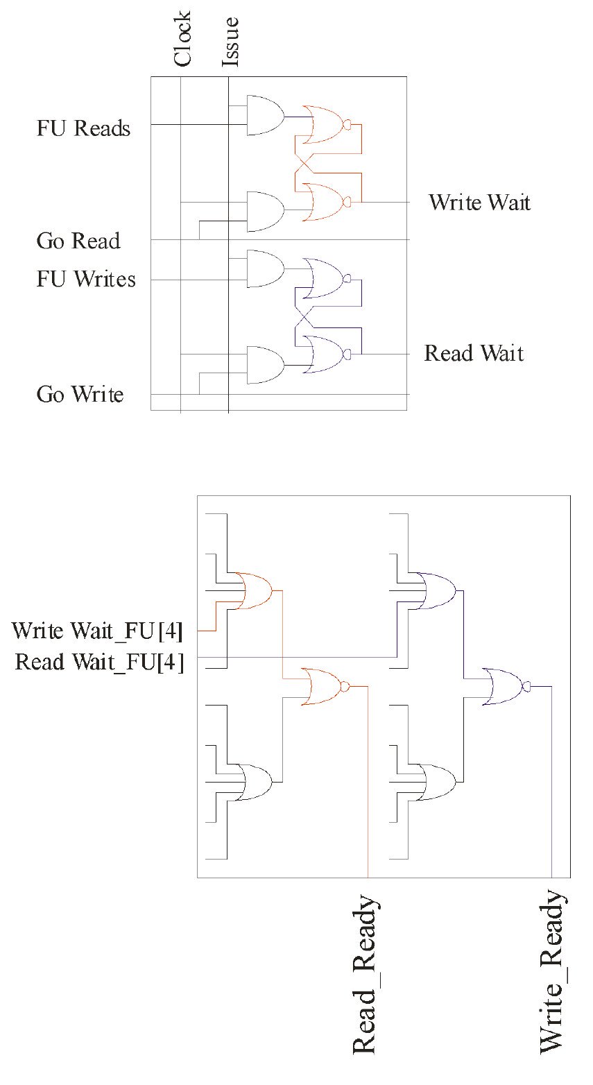
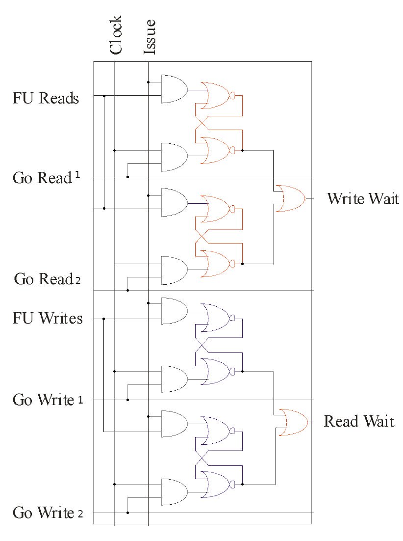
The scoreboard uses two big NOR gates respectively to determine when there are no read/write hazards. These two NOR gates are permanently active (per Function Unit) even if the Function Unit is idle.
In the case of the Write path, these "permanently-on" signals are gated by a Write-Release-Request signal that would otherwise leave the Priority Picker permanently selecting one of the Function Units (the highest priority). However the same thing has to be done for the read path, as well.
Below are the modifications required to add a read-release path that will prevent a Function Unit from requesting a GoRead signal when it has no need to read registers. Note that once both the Busy and GoRead signals combined are dropped, the ReadRelease is dropped.
Note that this is a loop: GoRead (ANDed with Busy) goes through to the priority picker, which generates GoRead, so it is critical (in a modern design) to use a clock-sync'd latch in this path. The original 6600 used rising-edge and falling-edge of the clock to avoid this issue.


Source:
Concurrent Computational Unit
With the original 6600 having only a 2-stage pipelined FPU (which took many years to notice from examining the now-archaic notation from James Thornton's book, "Design of a Computer"), there is no actual use of this pipeline capability at the front-end Function Unit. Instead it is treated effectively as a Finite State Machine, only one result to be computed at a time.
Mitch Alsup recommends, when using pipelines, to allow multiple Function Unit "front-ends", each one having inputs that were pushed into a particular stage of the pipeline, and, therefore, those multiple Function Units also track and store the result as it comes out.
The trick then is to have a method that ensures that FU front-end #1 can get result #1 when it pops out the end of the (serial) pipeline. Mitch recommends using timing chains, here.
Note in this diagram that there are multiple ISSUE, GO_READ and GO_WRITE signals. These link up to the Function Unit's ISSUE, GO_RD and GO_WR, where the latches are, that will (on an available slot) feed the pipeline with incoming data.
The actual design being used is slightly different, in the following ways:
- Due to micro-coding and thus external contention, the pipelines have a ready/valid signalling arrangement that can result in a stall cascading back down the pipeline. Thus a timing chain is not appropriate.
- A decision was therefore made to pass a "context" alongside the operands, which is the "Function Unit Index". It is this information that is used to "reassociate" the result with the correct FU, when the result is produced.
- With "Shadow cancellation" being in effect, additional global context is passed (combinatorially) to every single stage of the pipeline, as an unary bitmask. If any Function Unit's "GO_DIE" signal is asserted, the corresponding bit in the unary mask is asserted, terminating effective immediate the intermediary data anywhere in the pipeline from progressing further, thus saving power.
Multi-in cascading Priority Picker
Using the Group Picker as a fundamental unit, a cascading chain is created, with each output "masking" an output from being selected in all down-chain Pickers. Whilst the input is a single unary array of bits, the output is multiple unary arrays where only one bit in each is set.
This can be used for "port selection", for example when there are multiple Register File ports or multiple LOAD/STORE cache "ways", and there are many more devices seeking access to those "ports" than there are actual ports. (If the number of devices seeking access to ports were equal to the number of ports, each device could be allocated its own dedicated port).
Click on image to see full-sized version:

Links:
Modifications to Dependency Cell
Note: this version still requires CLK to operate on a HI-LO cycle. Further modifications are needed to create an ISSUE-GORD-PAUSE ISSUE-GORD-PAUSE sequence. For now however it is easier to stick with the original diagrams produced by Mitch Alsup.
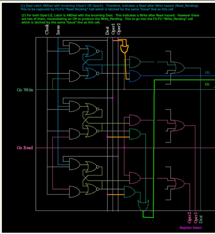
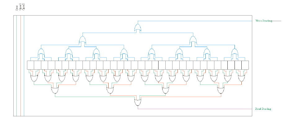
The dependency cell is responsible for recording that a Function Unit requires the use of a dest or src register, which is given in UNARY. It is also responsible for "defending" that unary register bit for read and write hazards, and for also, on request (GoRead/GoWrite) generating a "Register File Select" signal.
The sequence of operations for determining hazards is as follows:
- Issue goes HI when CLK is HI. If any of Dest / Oper1 / Oper2 are also HI, the relevant SRLatch will go HI to indicate that this Function Unit requires the use of this dest/src register
- Bear in mind that this cell works in conjunction with the FU-FU cells
- Issue is LOW when CLK is HI. This is where the "defending" comes into play. There will be another Function Unit somewhere that has had its Issue line raised. This cell needs to know if there is a conflict (Read Hazard or Write Hazard).
- Therefore, this cell must, if either of the Oper1/Oper2 signals are HI, output a "Read after Write" (RaW) hazard if its Dest Latch (Dest-Q) is HI. This is the Read_Pending signal.
- Likewise, if either of the two SRC Latches (Oper1-Q or Oper2-Q) are HI, this cell must output a "Write after Read" (WaR) hazard if the (other) instruction has raised the unary Dest line.
The sequence for determining register select is as follows:
- After the Issue+CLK-HI has resulted in the relevant (unary) latches for dest and src (unary) latches being set, at some point a GoRead (or GoWrite) signal needs to be asserted
- The GoRead (or GoWrite) is asserted when CLK is LOW. The AND gate on Reset ensures that the SRLatch remains ENABLED.
- This gives an opportunity for the Latch Q to be ANDed with the GoRead (or GoWrite), raising an indicator flag that the register is being "selected" by this Function Unit.
- The "select" outputs from the entire column (all Function Units for this unary Register) are ORed together. Given that only one GoRead (or GoWrite) is guaranteed to be ASSERTed (because that is the Priority Picker's job), the ORing is acceptable.
- Whilst the GoRead (or GoWrite) signal is still asserted HI, the CLK line goes LOW. With the Reset-AND-gate now being HI, this clears the latch. This is the desired outcome because in the previous cycle (which happened to be when CLK was LOW), the register file was read (or written)
The release of the latch happens to have a by-product of releasing the "reservation", such that future instructions, if they ever test for Read/Write hazards, will find that this Cell no longer responds: the hazard has already passed as this Cell already indicated that it was safe to read (or write) the register file, freeing up future instructions from hazards in the process.
Shadowing
Shadowing is important as it is the fundamental basis of:
- Precise exceptions
- Write-after-write hazard avoidance
- Correct multi-issue instruction sequencing
- Branch speculation
Modifications to the shadow circuit below allow the shadow flip-flops to be automatically reset after a Function Unit "dies". Without these modifications, the shadow unit may spuriously fire on subsequent re-use due to some of the latches being left in a previous state.
Note that only "success" will cause the latch to reset. Note also that the introduction of the NOT gate causes the latch to be more like a DFF (register).

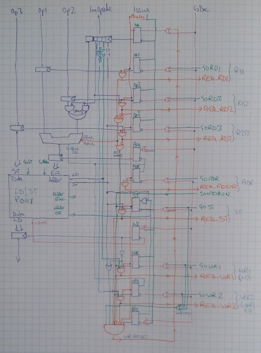
LD/ST Computation Unit
Discussions:
- http://lists.libre-riscv.org/pipermail/libre-riscv-dev/2020-April/006167.html
- https://groups.google.com/forum/#!topic/comp.arch/qeMsE7UxvlI
Walk-through Videos:
The Load/Store Computation Unit is a little more complex, involving three functions: LOAD, STORE, and LOAD-UPDATE. The SR Latches create a forward-progressing Finite State Machine, with three possible paths:
- LD Mode will activate Issue, GoRead1, GoAddr then finally GoWrite1
- LD-UPDATE Mode will additionally activate GoWrite2.
- ST Mode will activate Issue, GoRead1, GoRead2, GoAddr then GoStore. ST-UPDATE Mode will additionally activate GoWrite2.
These signals will be allowed to activate when the correct "Req" lines are active. Minor complications are involved (extra latches) that respond to an external API interface that has a more "traditional" valid/ready signalling interface, with single-clock responses.
Source:
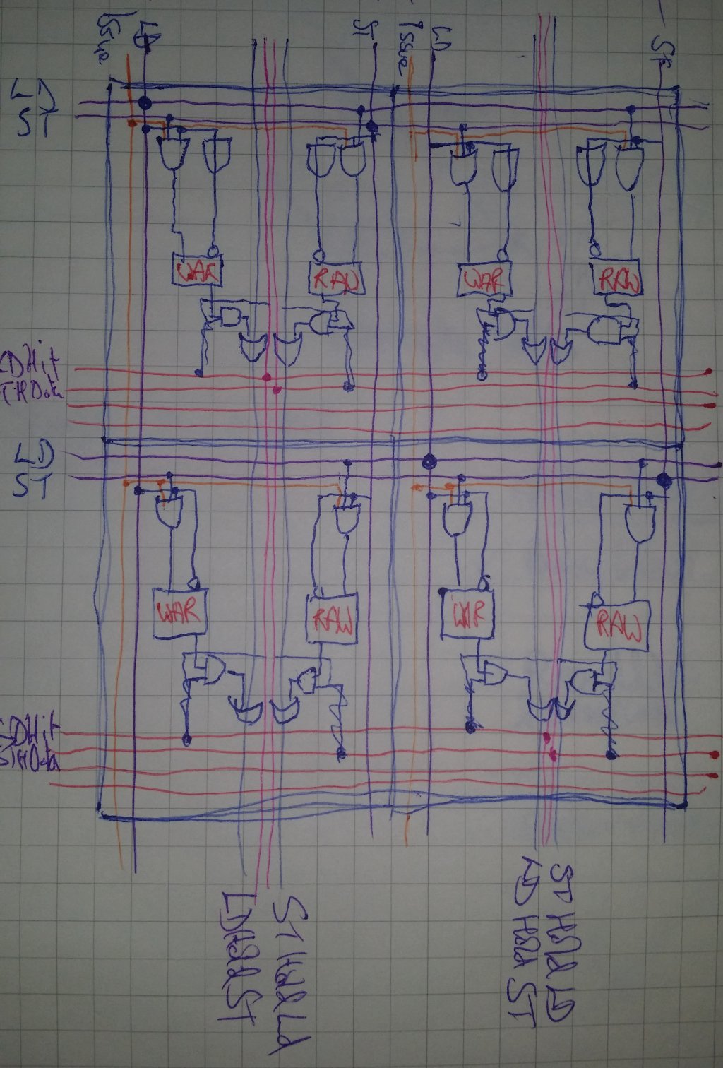
Memory-Memory Dependency Matrix
Due to the possibility of more than on LD/ST being in flight, it is necessary to determine which memory operations are conflicting, and to preserve a semblance of order. It turns out that as long as there is no possibility of overlaps (note this wording carefully), and that LOADs are done separately from STOREs, this is sufficient.
The first step then is to ensure that only a mutually-exclusive batch of LDs or STs (not both) is detected, with the order between such batches being preserved. This is what the memory-memory dependency matrix does.
"WAR" stands for "Write After Read" and is an SR Latch. "RAW" stands for "Read After Write" and likewise is an SR Latch. Any LD which comes in when a ST is pending will result in the relevant RAW SR Latch going active. Likewise, any ST which comes in when a LD is pending results in the relevant WAR SR Latch going active.
LDs can thus be prevented when it has any dependent RAW hazards active, and likewise STs can be prevented when any dependent WAR hazards are active. The matrix also ensures that ordering is preserved.
Note however that this is the equivalent of an ALU "FU-FU" Matrix. A separate Register-Mem Dependency Matrix is still needed in order to preserve the register read/write dependencies that occur between instructions, where the Mem-Mem Matrix simply protects against memory hazards.
Note also that it does not detect address clashes: that is the responsibility of the Address Match Matrix.
Source:
Address Match Matrix
This is an important adjunct to the Memory Dependency Matrices: it ensures that no LDs or STs overlap, because if they did it could result in memory corruption. Example: a 64-bit ST at address 0x0001 comes in at the same time as a 64-bit ST to address 0x0002: the second write will overwrite all writes to bytes in memory 0x0002 thru 0x0008 of the first write, and consequently the order of these two writes absolutely has to be preserved.
The suggestion from Mitch Alsup was to use a match system based on bits 4 thru 10/11 of the address. The idea being: we don't care if the matching is "too inclusive", i.e. we don't care if it includes addresses that don't actually overlap, because this just means "oh dear some LD/STs do not happen concurrently, they happen a few cycles later" (translation: Big Deal)
What we care about is if it were to miss some addresses that do actually overlap. Therefore it is perfectly acceptable to use only a few bits of the address. This is fortunate because the matching has to be done in a huge NxN Pascal's Triangle, and if we were to compare against the entirety of the address it would consume vast amounts of power and gates.
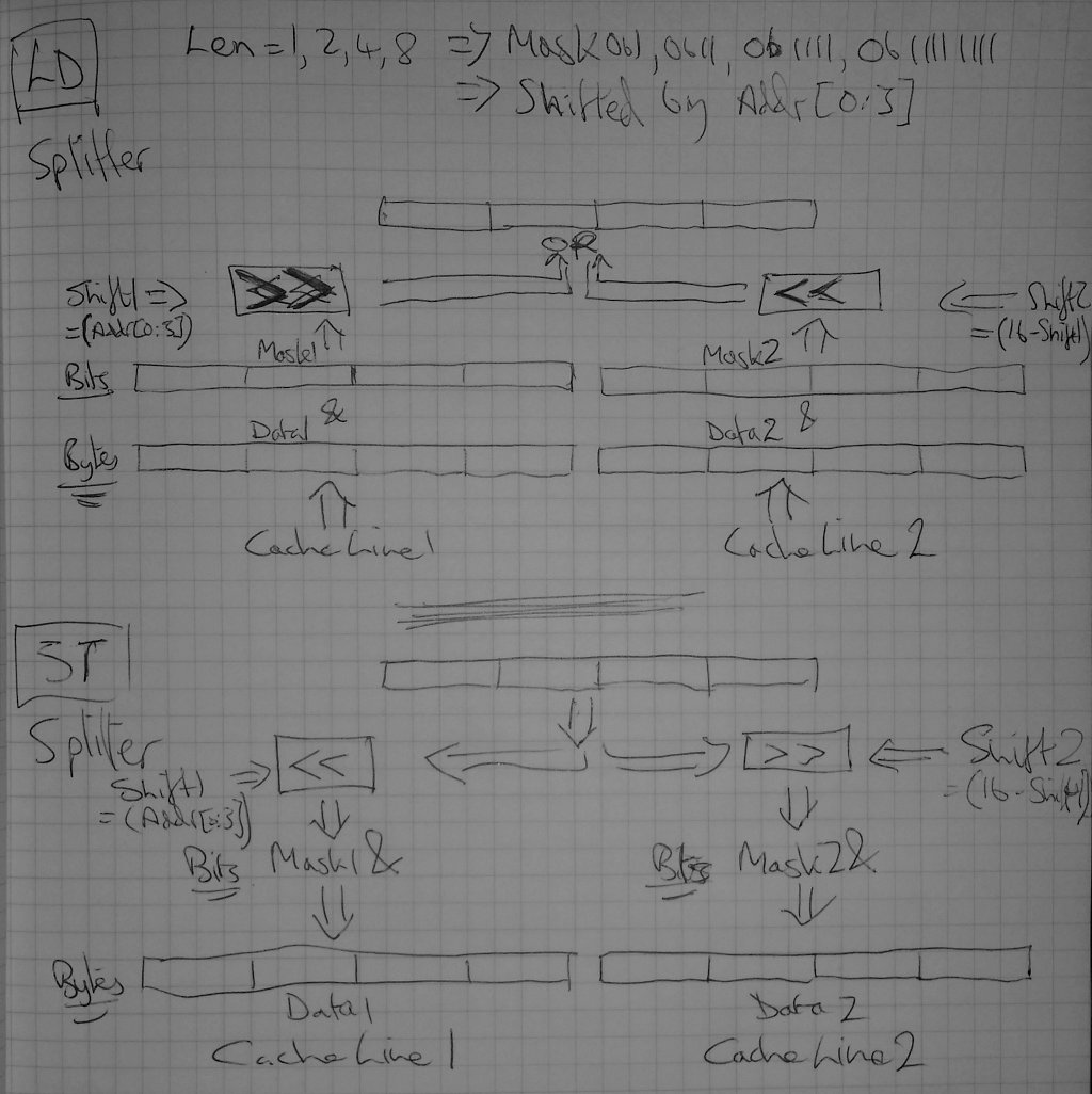
An enhancement of this idea is to turn the length of the operation (LD/ST 1 byte, 2 bytes, 4 or 8 bytes) into a byte-map "mask", using the bottom 4 bits of the address to offset this mask and "line up" with the Memory byte read/write enable wires on the underlying Memory used in the L1 Cache.
Then, the bottom 4 bits and the LD/ST length, now turned into a 16-bit unary mask, can be "matched" using simple AND gate logic (instead of XOR for binary address matching), with the advantage that it is both trivial to use these masks as L1 Cache byte read/write enable lines, and furthermore it is straightforward to detect misaligned LD/STs crossing cache line boundaries.
Crossing over cache line boundaries is trivial in that the creation of the byte-map mask is permitted to be 24 bits in length (actually, only 23 needed). When the bottom 4 bits of the address are 0b1111 and the LD/ST is an 8-byte operation, 0b1111 1111 (representing the 64-bit LD/ST) will be shifted up by 15 bits. This can then be chopped into two segments:
- First segment is 0b1000 0000 0000 0000 and indicates that the first byte of the LD/ST is to go into byte 15 of the cache line
- Second segment is 0b0111 1111 and indicates that bytes 2 through 8 of the LD/ST must go into bytes 0 thru 7 of the second cache line at an address offset by 16 bytes from the first.
Thus we have actually split the LD/ST operation into two. The AddrSplit class takes care of synchronising the two, by issuing two separate sets of LD/ST requests, waiting for both of them to complete (or indicate an error), and (in the case of a LD) merging the two.
The big advantage of this approach is that at no time does the L1 Cache need to know anything about the offsets from which the LD/ST came. All it needs to know is: which bytes to read/write into which positions in the cache line(s).
Source:
L0 Cache/Buffer
See:
- https://bugs.libre-soc.org/show_bug.cgi?id=216
- https://bugs.libre-soc.org/show_bug.cgi?id=257
- http://lists.libre-riscv.org/pipermail/libre-riscv-dev/2020-April/006118.html
The L0 cache/buffer needs to be kept extremely small due to it having significant extra CAM functionality than a normal L1 cache. However, crucially, the Memory Dependency Matrices and address-matching take care of certain things that greatly simplify its role.
The problem is that a standard "queue" in a multi-issue environment would need to be massively-ported: 8-way read and 8-way write. However that's not the only problem: the major problem is caused by the fact that we are overloading "vectorisation" on top of multi-issue execution, where a "normal" vector system would have a Vector LD/ST operation where sequences of consecutive LDs/STs are part of the same operation, and thus a "full cache line" worth of reads/writes is near-trivial to perform and detect.
Thus with the "element" LD/STs being farmed out to individual LD/ST Computation Units, a batch of consecutive LD/ST operations arrive at the LD/ST Buffer which could - hypothetically - be merged into a single cache line, prior to passing them on to the L1 cache.
This is the primary task of the L0 Cache/Buffer: to resolve multiple (potentially misaligned) 1/2/4/8 LD/ST operations (per cycle) into one single L1 16-byte LD/ST operation.
The amount of wiring involved however is so enormous (3,000+ wires if "only" 4-in 4-out multiplexing is done from the LD/ST Function Units) that considerable care has to be taken to not massively overload the ASIC layout.
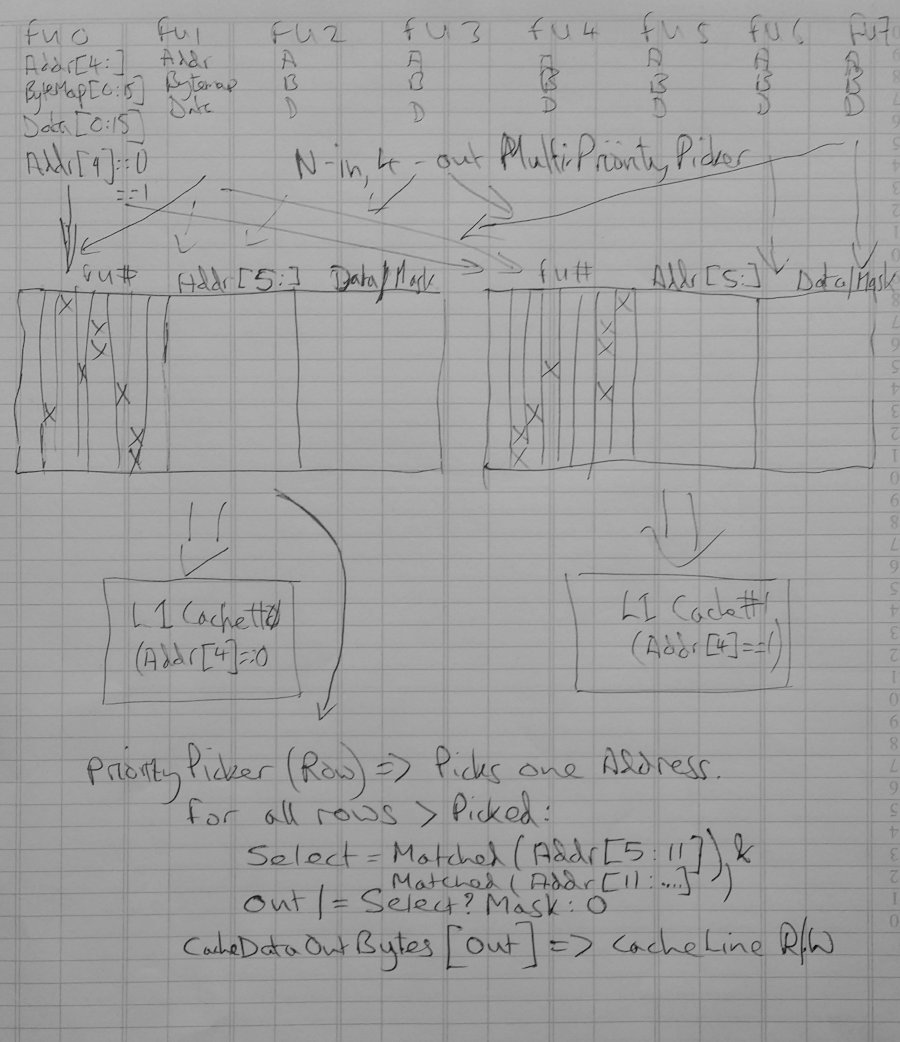
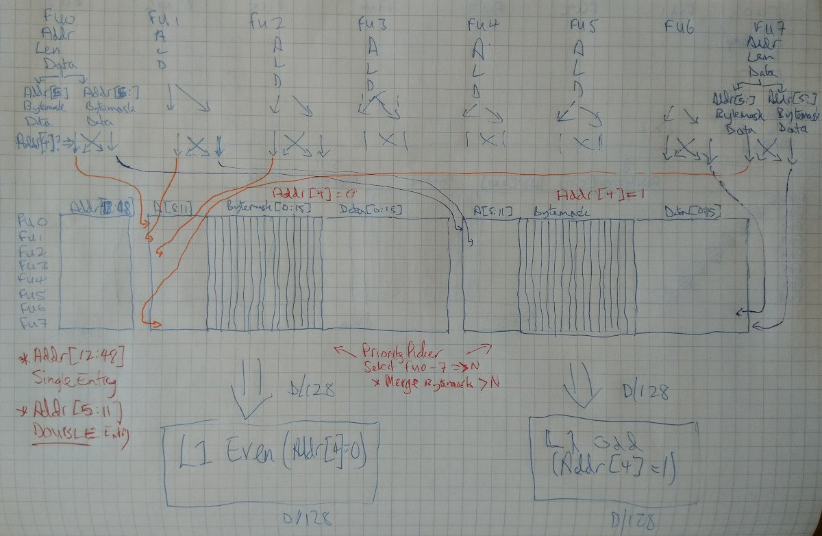
To help with this, a recommendation from comp.arch came to do a split odd-even double-L1-cache system: have two L1 caches, one dealing with even-numbered 16-byte cache lines (addressed by bit 4 == 0) and one dealing with odd-numbered 16-byte cache lines (addr[4] == 1). This trick doubles the sequential throughput whilst halving the bandwidth of a drastically-overloaded multiplexer bus. Thus, we can also have two L0 LD/ST Cache/Buffers (one each looking after its corresponding L1 cache).
The next phase - task - of the L0 Cache/Buffer - is to identify and merge any requests with the same top 5 bits. This becomes a trivial task (under certain conditions, already satisfied by other components), by simply picking the first request, and using that row's address as a search pattern to match against all upper bits (5 onwards). When such a match is located, then due to the job(s) carried out by prior components, the byte-mask for all requests with the same upper address bits may simply be ORed together.
This requires a little back-tracking to explain. The prerequisite conditions are as follows:
- Mask, in each row of the L0 Cache/Buffer, encodes the bottom 4 LSBs of the address and the length of the LD/ST operation (1/2/4/8 bytes), in a "bitmap" form.
- These "Masks" have already been analysed for overlaps by the Address Match Matrix: we know therefore that there are no overlaps (hence why addresses with the same MSBs from bits 5 and above may have their masks ORed together)
Twin L0 cache/buffer design
See https://groups.google.com/d/msg/comp.arch/cbGAlcCjiZE/OPNAvWSHAQAJ. Flaws in the above were detected, and needed correction.
Notes:
- The flaw detected above is that for each pair of LD/ST operations coming from the Function Unit (to cover mis-aligned requests), the Addr[4] bit is mutually-exclusive. i.e. it is guaranteed that Addr[4] for the first FU port's LD/ST request will never equal that of the second.
- Therefore, if the two requests are split into left/right separate L0 Cache/Buffers, the advantages and optimisations for XOR-comparison of bits 12-48 of the address may not take place.
- Solution: merge both L0-left and L0-right into one L0 Cache/Buffer, with twin left/right banks in the same L0 Cache/Buffer
- This then means that the number of rows may be reduced to 8
- It also means that Addr[12-48] may be stored (and compared) only once
- It does however mean that the reservation on the row has to wait for both ports (left and right) to clear out their LD/ST operation(s).
- Addr[4] still selects whether the request is to go into left or right bank
- When the misaligned address bits 4-11 are all 0b11111111, this is not a case that can be handled, because it implies that Addr[12:48] will be different in the row. This case throws a misaligned exception.
Other than that, the design remains the same, as does the algorithm to merge the bytemasks. This remains as follows:
- PriorityPicker selects one row
- For all rows greater than the selected row, if Addr[5:48] matches then the bytemask is "merged" into the output-bytemask-selector
- The output-bytemask-selector is used as a "byte-enable" line on a single 128-bit byte-level read-or-write (never both).
Twin 128-bit requests (read-or-write) are then passed directly through to a pair of L1 Caches.
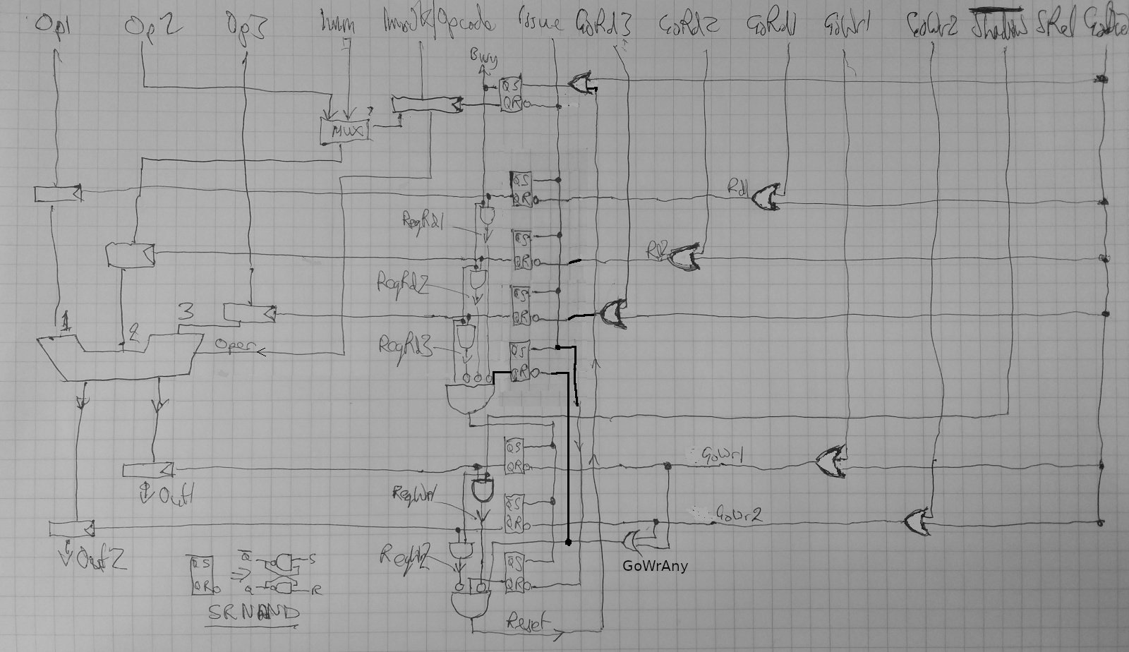
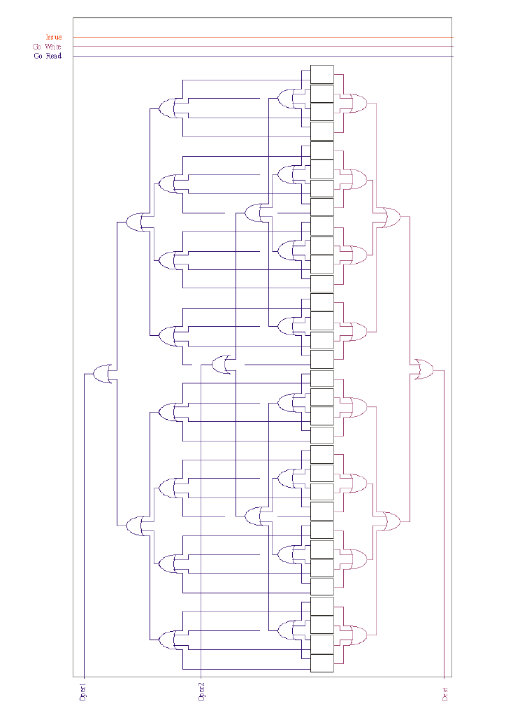
Multi-input/output Dependency Cell and Computation Unit
apologies that this is best done using images rather than text. i'm doing a redesign of the (augmented) 6600 engine because there are a couple of design criteria/assumptions that do not fit our requirements:
- operations are only 2-in, 1-out
- simultaneous register port read (and write) availability is guaranteed.
we require:
- operations with up to four in and up to three out
- sporadic availability of far less than 4 Reg-Read ports and 3 Reg-Write
here are the two associated diagrams which describe the original 6600 computational unit and FU-to-Regs Dependency Cell:
- comp unit https://libre-soc.org/3d_gpu/comp_unit_req_rel.jpg
- dep cell https://libre-soc.org/3d_gpu/dependence_cell_pending.jpg
as described here https://libre-soc.org/3d_gpu/architecture/6600scoreboard/ we found a signal missing from Mitch's book chapters, and tracked it down from the original Thornton "Design of a Computer": Read_Release. this is a synchronisation / acknowledgement signal for Go_Read which is directly analogous to Req_Rel for Go_Write.
also in the dependency cell, we found that it is necessary to OR the two "Read" Oper1 and Oper2 signals together and to AND that with the Write_Pending Latch (top latch in diagram 2.) as shown in the wonderfully hand-drawn orange OR gate.
thus, Read-After-Write hazard occurs if there is a Write_Pending AND any Read (oper1 OR oper2) is requested.
now onto the additional modifications.
- comp unit https://libre-soc.org/3d_gpu/compunit_multi_rw.jpg
- dep cell https://libre-soc.org/3d_gpu/dependence_cell_multi_pending.jpg
firstly, the computation unit modifications:
- multiple Go_Read signals are present, GoRD1-3
- multiple incoming operands are present, Op1-3
- multiple Go_Write signals are present, GoWR1-3
- multiple outgoing results are present, Out1-2
note that these are NOT necessarily 64-bit registers: they are in fact Carry Flags because we are implementing POWER9. however (as mentioned yesterday in the huge 250+ discussion, as far as the Dep Matrices are concerned you still have to treat Carry-In and Carry-out as Read/Write Hazard-protected actual Registers)
in the original 6600 comp unit diagram (1), because the "Go_Read" assumes that both registers will be read (and supplied) simultaneously from the Register File, the sequence - the Finite State Machine - is real simple:
- ISSUE -> BUSY (latched)
- RD-REQ -> GO_RD
- WR-REQ -> GO_WR
- repeat
[aside: there is a protective "revolving door" loop where the SR latch for each state in the FSM is guaranteed stable (never reaches "unknown") ]
in this diagram (3), we instead need:
- ISSUE -> BUSY (latched)
- RD-REQ1 -> GO_RD1 (may occur independent of RD2/3)
- RD-REQ2 -> GO_RD2 (may occur independent of RD1/3)
- RD-REQ3 -> GO_RD3 (may occur independent of RD1/2)
- when all 3 of GO_RD1-3 have been asserted, ONLY THEN raise WR-REQ1-2
- WR-REQ1 -> GO_WR1 (may occur independent of WR2)
- WR-REQ2 -> GO_WR2 (may occur independent of WR1)
- when all (2) of GO_WR1-2 have been asserted, ONLY THEN reset back to the beginning.
note the crucial difference is that read request and acknowledge (GO_RD) are all independent and may occur:
- in any order
- in any combination
- all at the same time
likewise for write-request/go-write.
thus, if there is only one spare READ Register File port available (because this particular Computation Unit is a low priority, but the other operations need only two Regfile Ports and the Regfile happens to be 3R1W), at least one of OP1-3 may get its operation.
thus, if we have three 2-operand operations and a 3R1W regfile:
- clock cycle 1: the first may grab 2 ports and the second grabs 1 (Oper1)
- clock cycle 2: the second grabs one more (Oper2) and the third grabs 2
compare this to the original 6600: if there are three 2-operand operations outstanding, they MUST go:
- clock cycle 1: the first may grab 2 ports, NEITHER the 2nd nor 3rd proceed
- clock cycle 2: the second may grab 2 ports, 3rd may NOT proceed
- clock cycle 3: the 3rd grabs 2 ports
this because the Comp Unit - and associated Dependency Matrices - FORCE the Comp Unit to only proceed when ALL necessary Register Read Ports are available (because there is only the one Go_Read signal).
so my questions are:
does the above look reasonable? both in terms of the DM changes and CompUnit changes.
the use of the three SR latches looks a little weird to me (bottom right corner of (3) which is a rewrite of the middle of the page.
it looks a little weird to have an SR Latch looped back "onto itself". namely that when the inversion of both WR_REQ1 and WR_REQ2 going low triggers that AND gate (the one with the input from Q of an SR Latch), it resets that very same SR-Latch, which will cause a mini "blip" on Reset, doesn't it?
argh. that doesn't feel right. what should it be replaced with?

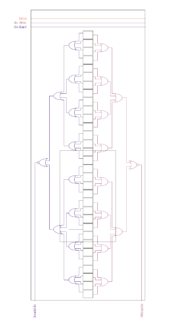
Corresponding FU-FU (Function-to-Function) Dependency Cell Modifications
Original 6600 FU-FU Cell diagram:
Augmented multi-GORD/GOWR 6600 FU-FU Cell diagram:
FU-Regs Vectors
There are two FU-Regs Vectors. The first is an accumulation of all row information. This indicates that (on a per-Operand basis in the Libre-SOC design) there is a write pending for that Operand (note that this is not per register, it is per operand). Likewise, the OR-accumulation of every unary-encoded register SR-Latch bit in the row, for reading for each FU's Operand, indicates a desire of that Function Unit's need to read from a given port.
These accumulated signals, coming out on a per-row basis for each Operand port, are sent straight to every cell in the corresponding FU-FU Matrix row.
The second vector set accumulates the column information. With the FU-Regs Cells capturing the instruction operand read/write register numbers (in unary form), the ORing per column of those bits creates a "global picture", per register, of the fact that any Function Unit needs to read (or write) a particular Operand latch port.
FU-FU Vectors
Two vectors exist that accumulate row and column information. With the FU-FU Cell recording whether the Function Unit wants to read (or write) the per-cell information is not so crucial as the accumulation of that information. When all other Function Units in that column no longer indicate that they were waiting for a read, that FU is clear to write. Correspondingly, when all FUs in the column no longer indicate waiting for a write, that FU is clear to read. With a full NxN matrix of cells, this inversion preserves Read-after-Write and Write-after-Read hazard information relationships between all Function Units and all other Function Units.
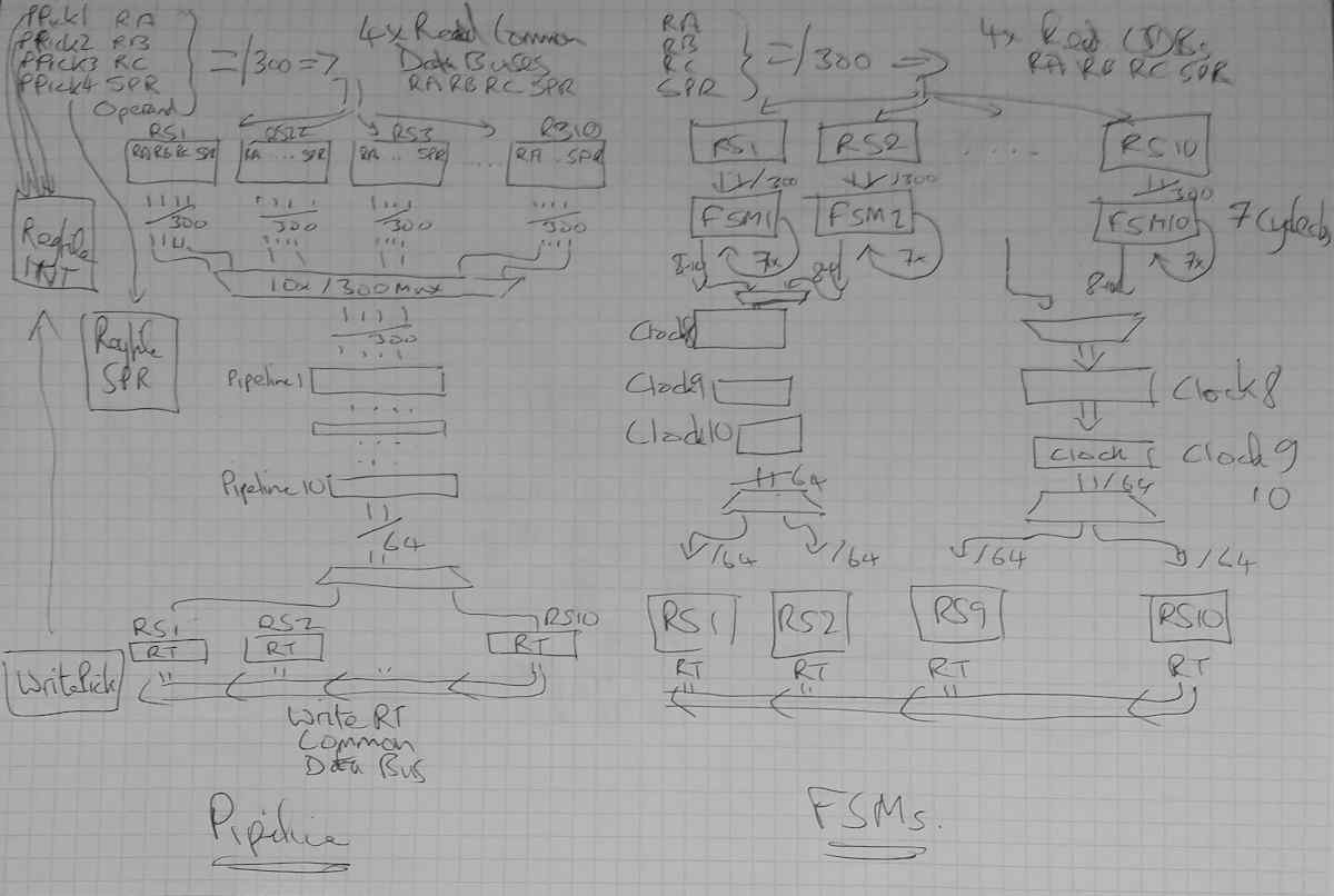
Illustrative diagram of Pipelines vs FSMs
Explanatory note here https://lists.libre-soc.org/pipermail/libre-soc-dev/2022-March/004528.html